RFID Smart Car Gate Opener
1. Introduction & Project Scope
Concept & Inspiration: This project serves as a functional prototype of an automated parking gate system, directly inspired by the gate mechanism at the Soldiers and Sailors Garage where I parked daily during my university studies. Fascinated by the precise coordination of sensors and actuators required for secure vehicle entry, I challenged myself to replicate and improve upon this real-world system using embedded technology.
The Solution: The final prototype addresses the need for secure, efficient, and contactless vehicle management. Unlike simple manual gates, this system integrates an RFID-based authentication system with an automated mechanical gate. It features an interactive 16x2 LCD interface to prompt users, a servo-actuated gate arm, and an intelligent ultrasonic sensor loop that prevents the gate from closing until the vehicle has safely passed.
My Role (Solo Engineer): As an individual project, I was solely responsible for every phase of the engineering lifecycle:
- Electrical Engineering: Designed the mixed-voltage power architecture, selected components, and fabricated the custom PCB.
- Firmware Engineering: Wrote the C++ firmware to coordinate the RFID reader, servo timing, and safety sensor logic.
- Mechanical Design: Modeled the enclosure in SolidWorks and fabricated it using laser cutting and woodworking tools to ensure a compact, professional finish.
Project Demonstration: Authentication Cycle & Safety Logic
System Architecture
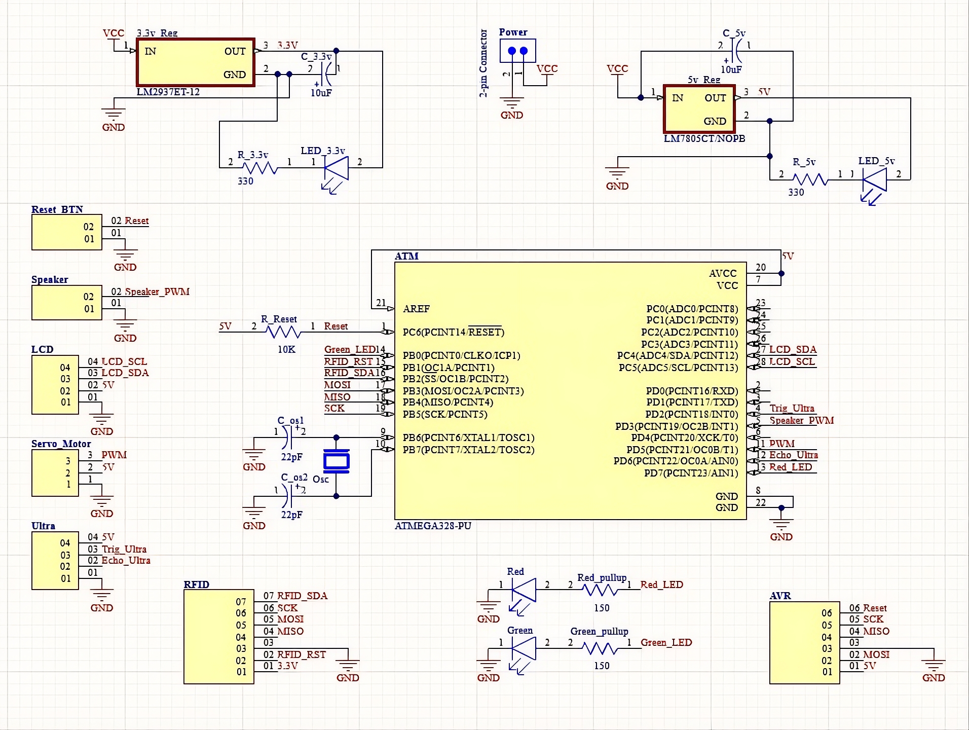
The system is built around a standalone ATmega328P microcontroller. It features a dual-voltage power architecture to support mixed-signal components.
- Processing: ATmega328P (16MHz Internal Clock).
- Authentication: MFRC522 RFID Module (13.56 MHz).
- User Interface: 16x2 LCD (I2C) + Piezo Speaker + Status LEDs.
- Actuation: Micro Servo Motor (PWM Controlled).
- Safety: HC-SR04 Ultrasonic Sensor for vehicle detection.
Design Challenges Solved
- Mixed Voltage Logic: The RFID sensor requires 3.3V logic, while the servo and LCD require 5V. I designed a custom regulator circuit using LM7805 and LM2937 chips to bridge these domains safely.
- Resource Optimization: With limited pins on the ATmega328P, I utilized the I2C protocol for the LCD to save GPIO lines for sensors.
- Power Stability: To prevent servo motor noise from resetting the microcontroller, I implemented decoupling capacitors and separate power rails on the PCB.
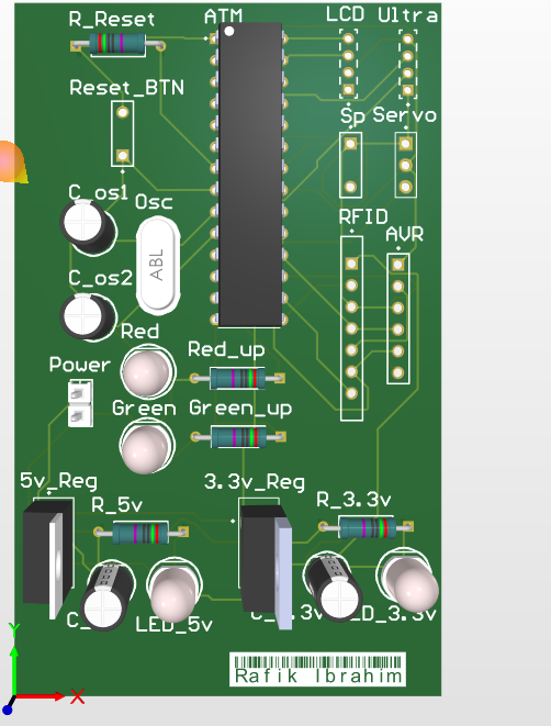
3. Hardware Design & PCB Implementation
Moving from a breadboard prototype to a final product required a custom PCB design. The primary challenge was integrating the voltage regulation directly onto the board to eliminate external power bricks and ensure a compact form factor.
Power Architecture
The system is powered by a 9V source. I engineered a dual-regulator circuit directly on the PCB:
- 5V Rail: An LM7805CV linear regulator powers the ATmega328P, LCD, and Servo.
- 3.3V Rail: An LM2937ET-3.3 regulator provides clean power to the sensitive MFRC522 RFID module.
- Thermal Management: Regulators were spaced to dissipate heat, and decoupling capacitors were placed close to the power pins to filter high-frequency noise.
PCB Design Strategy
Designed in Altium Designer, the PCB features:
- Modular Headers: Instead of soldering components directly, I used female headers for the RFID, Ultrasonic, and Servo connections. This allows for easy replacement of faulty sensors.
- ISP Programming Header: Included to allow in-circuit programming of the ATmega328P without removing the chip.
- Compact Layout: Traces were routed to minimize cross-talk between the high-current servo lines and the sensitive RFID SPI lines.
4. Firmware & Software Implementation (Sample Code)
I wrote the firmware in C++ using the Arduino IDE. The logic relies on a state machine that handles card scanning, authentication, and safety checks before moving the gate. Below are sample snippets of the core logic I implemented.
void loop() {
    // 1. Check for new card presence
    if (!mfrc522.PICC_IsNewCardPresent()) return;
    if (!mfrc522.PICC_ReadCardSerial()) return;

    // 2. Read UID and Compare with Authorized Database
    String content = "";
    for (byte i = 0; i < mfrc522.uid.size; i++) {
        content.concat(String(mfrc522.uid.uidByte[i] < 0x10 ? " 0" : " "));
        content.concat(String(mfrc522.uid.uidByte[i], HEX));
    }
    content.toUpperCase();

    // 3. Determine Access State
    if (content.substring(1) == AUTHORIZED_UID) {
        grantAccess(); // Trigger Green LED, Servo Open, Success Tone
    } else {
        denyAccess();  // Trigger Red LED, Error Tone
    }
}
void grantAccess() {
    lcd.clear();
    lcd.print("Access Granted");

    // 1. Open Gate
    servo.write(90);
    delay(2000);

    // 2. Safety Loop: Wait for vehicle to pass using Ultrasonic Sensor
    while (isObjectDetected()) {
        delay(100); // Hold gate open if car is detected
    }

    // 3. Close Gate after vehicle clears
    delay(1000);
    servo.write(0);
    resetSystem();
}

bool isObjectDetected() {
    // Ultrasonic Logic: Trigger Pulse -> Echo Read
    digitalWrite(TRIG_PIN, LOW);
    delayMicroseconds(2);
    digitalWrite(TRIG_PIN, HIGH);
    delayMicroseconds(10);
    digitalWrite(TRIG_PIN, LOW);

    long duration = pulseIn(ECHO_PIN, HIGH);
    int distance = duration * 0.034 / 2;

    return (distance < 10); // Return TRUE if object is within 10cm
}