Retro Multiplayer Game Console
1. Introduction & Motivation
The Mission: Modern gaming has become increasingly complex, expensive, and isolated, often relying on high-end hardware and internet connectivity. "Project R&F" was conceived to revive the social aspect of gaming by engineering a console that bridges retro nostalgia with modern embedded technology. Our goal was to create a cost-effective, accessible, and purely offline multiplayer experience that encourages face-to-face interaction.
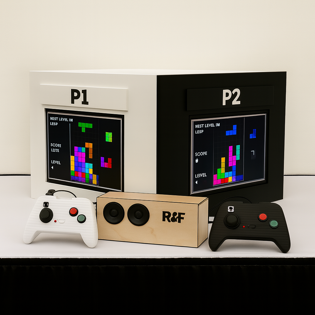
The Innovation: The primary innovation is to make old retro single-player games into multiplayer experiences. Unlike traditional retro emulators that use a single shared screen or split-screen software, this system drives two independent VGA monitors simultaneously. This allows for true "head-to-head" multiplayer functionality where each player has a dedicated view, yet the game state remains perfectly synchronized via a custom hardware link.
The Engineering Challenge: The project required the development of a distributed embedded network. To achieve real-time performance without an Operating System, we offloaded tasks across multiple specialized microcontrollers:
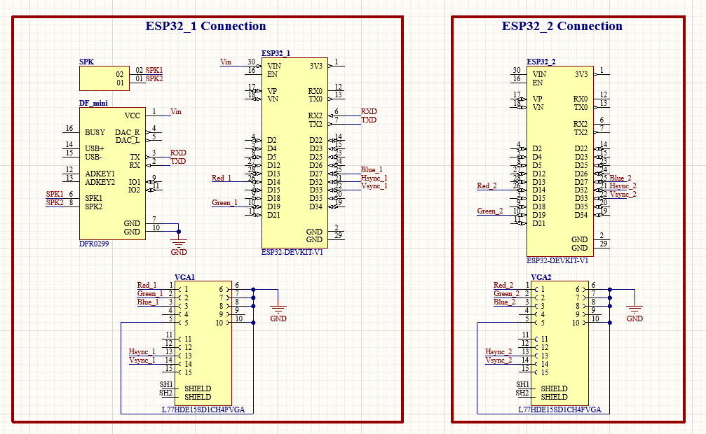
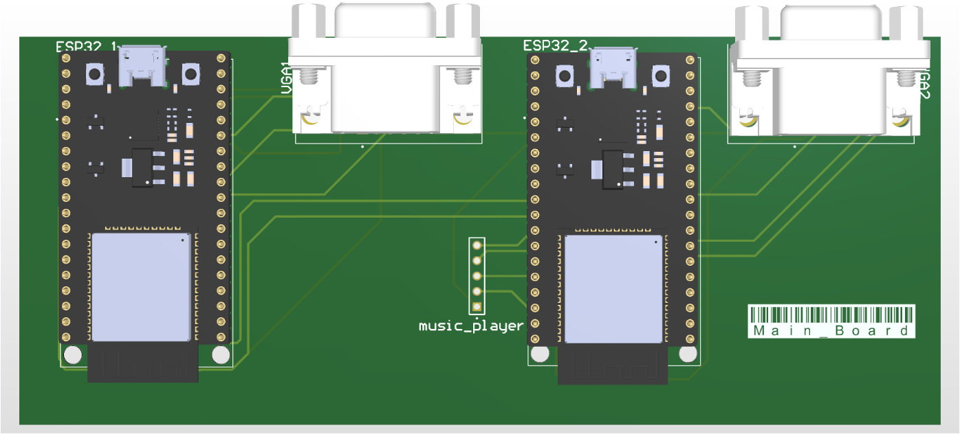
- Main Console: Two ESP32-WROVER units communicate via a high-speed UART bridge to sync physics with zero latency.
- Wireless Control: Custom-built controllers use ATmega328P chips to process analog inputs and transmit data via HC-05 Bluetooth modules.
- Visuals: Video signals are generated "bare metal" using Direct Memory Access (DMA) and GPIO bit-banging to produce standard VGA signals without a GPU.
My Role: Lead Electrical Engineer
Leading a team of three Computer Engineers, I was solely responsible for the entire hardware lifecycle. This included the schematic capture and PCB layout of all three system boards (Main Console, Audio Subsystem, and Controllers) using Altium Designer. I engineered the power architecture to support 72-hour runtimes, designed the mixed-signal VGA output stages, and managed the physical fabrication of the enclosures. Additionally, I bridged the gap between hardware and software, writing the low-level drivers for the Bluetooth stack and audio synchronization.
System Specifications
- Architecture: Distributed Network (2x ESP32 Masters + 2x ATmega328P Slaves).
- Video Output: Dual Stream Digital VGA (320x200 @ 60Hz).
- Power Autonomy: 72 Hours (Parallel Li-Ion Configuration).
- Synchronization: Hardwired UART Bridge (115200 baud).
- Wireless Latency: < 50ms (Bluetooth HC-05).
2. System Architecture & Component Selection
The decision to use a distributed multi-processor architecture was driven by the need to isolate high-speed video generation from asynchronous user input. Below is the rationale for the key components we selected for the final design.
Main Processing Unit: ESP32-WROVER-E
We selected the ESP32-WROVER-E for the main console due to its dual-core Xtensa LX6 architecture running at 240 MHz.
- Reasoning: The VGA signal generation requires strict timing (25.175 MHz pixel clock). A single-core MCU would struggle to handle this alongside game logic. With the ESP32, we could dedicate Core 1 entirely to video signal generation (using the I2S peripheral in parallel mode) while Core 0 handled the game physics, audio triggers, and UART communication.
- Memory: The WROVER module includes 8MB of PSRAM, which was essential for storing the double-buffered frame data required for smooth 60fps animation.
Controller Logic: ATmega328P
For the wireless controllers, we chose the ATmega328P (the chip found in the Arduino Uno).
- Reasoning: The controllers only need to sample analog inputs (joysticks) and digital buttons (tactile switches) and transmit them via UART. The ATmega328P is extremely power-efficient in this role and offers robust 10-bit ADC channels for precise joystick tracking.
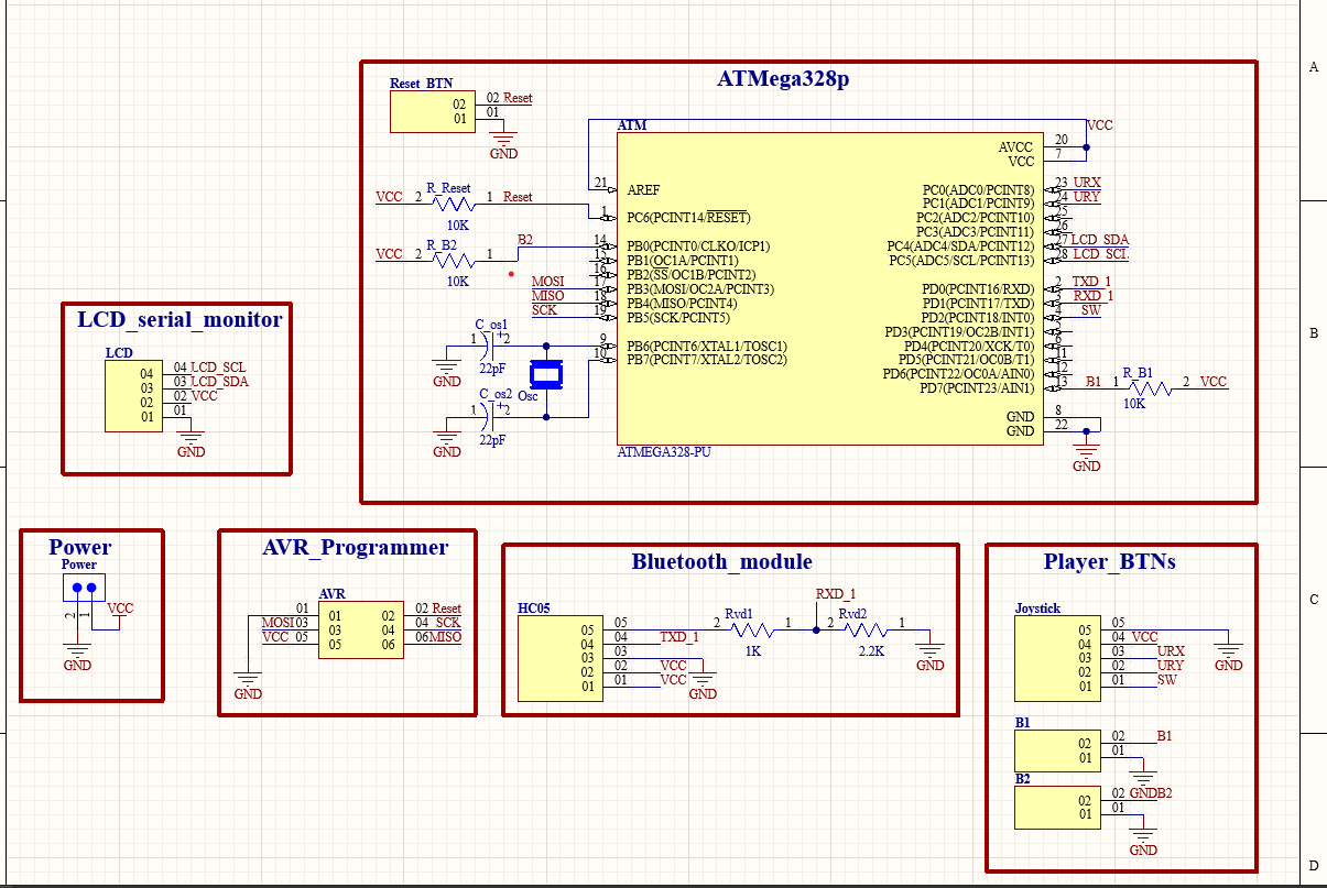
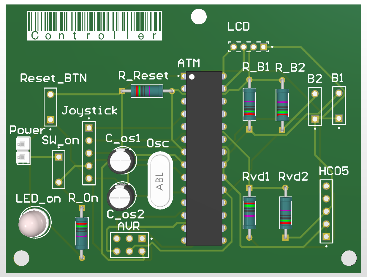
- Form Factor: Using the standalone DIP-28 chip allowed us to design a custom PCB footprint that fits comfortably in a handheld enclosure, rather than using a bulky development board.
Wireless Communication: HC-05 Bluetooth
We utilized the HC-05 Bluetooth Classic module in a Master/Slave configuration.
- Reasoning: While Wi-Fi was an option, it introduces significant power overhead and connection latency. The HC-05 operating over the Serial Port Profile (SPP) provides a dedicated, low-latency data pipe that is simpler to debug and consumes less power than Wi-Fi.
- Implementation: We configured the controller modules as Masters and the console modules as Slaves, binding them to specific MAC addresses to prevent cross-talk in noisy RF environments.
3. Detailed Hardware Implementation
As a group, we focused on building a robust hardware ecosystem. My specific focus was on moving from breadboard prototypes to three custom-fabricated Printed Circuit Boards (PCBs). This required careful consideration of power integrity, signal routing, and thermal management.
Power Architecture Design
We engineered a power system designed for extreme endurance. The controller uses two 18650 Lithium-Ion batteries (3300mAh each) wired in parallel, providing a total capacity of 6.6Ah at 3.7V.
- Regulation: We integrated a high-efficiency DC-DC Step-Up Boost Converter to elevate the 3.7V battery voltage to a stable 5V, required for the ATmega328P and HC-05 modules.
- UPS Functionality: The design includes a TP4056-based load-sharing circuit that allows the device to charge via USB-C while simultaneously powering the system.
- Efficiency Analysis: With a 92% efficiency boost converter, the calculated usable energy is approximately 22.47 Wh, enabling over 72 hours of continuous runtime—far exceeding the initial 6-hour requirement.
Signal Integrity & Mixed-Signal Design
Generating a clean VGA signal from a microcontroller requires precise signal integrity.
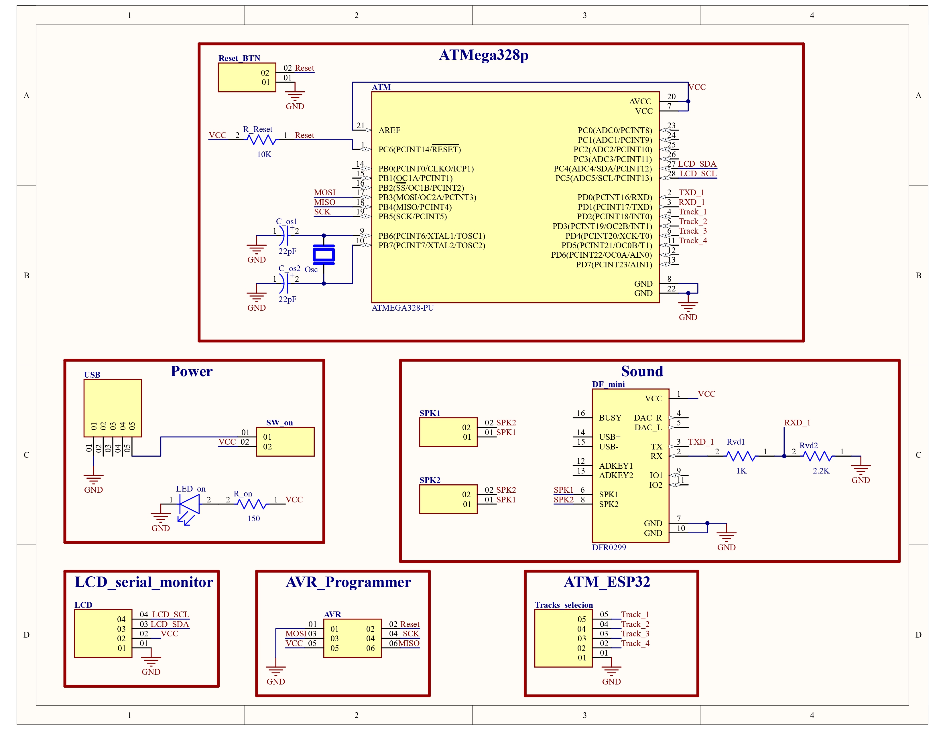
- Logic Level Shifting: The HC-05 Bluetooth module operates at 3.3V logic, while the ATmega328P runs at 5V. We designed voltage divider circuits (1kΩ / 2.2kΩ) on the PCB TX/RX lines to safely step down signals.
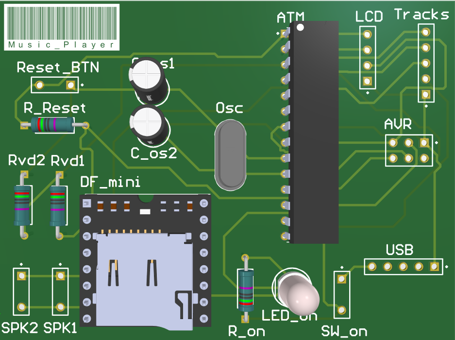
- Audio Isolation: To prevent digital switching noise from coupling into the audio output, we physically separated the Audio Subsystem onto its own PCB with a dedicated ground plane.
- VGA Output: We routed the 5-pin VGA signals (Red, Green, Blue, H-Sync, V-Sync) directly from the ESP32 GPIOs, carefully matching trace lengths to minimize skew.
Bill of Materials (Selected Key Components)
*Note: This list highlights the most critical components in the system architecture, not the exhaustive BOM.
| Component | Specification | Quantity | Role |
|---|---|---|---|
| ESP32-WROVER-E | Dual Core 240MHz, 8MB PSRAM | 2 | Main Console Processing & Video Generation |
| ATmega328P-PU | 8-bit AVR, 20MHz | 3 | Controller Logic & Audio Management |
| HC-05 Bluetooth | Bluetooth 2.0+EDR, SPP Profile | 2 | Wireless Data Transmission (Input) |
| MT3608 | 2A DC-DC Step Up Converter | 2 | Boosts 3.7V Li-Ion to 5V System Rail |
| DFPlayer Mini | MP3 Decoder Module | 1 | Hardware Audio Decoding |
| Analog Joystick | 2-Axis Potentiometer with Switch | 2 | User Input Control |
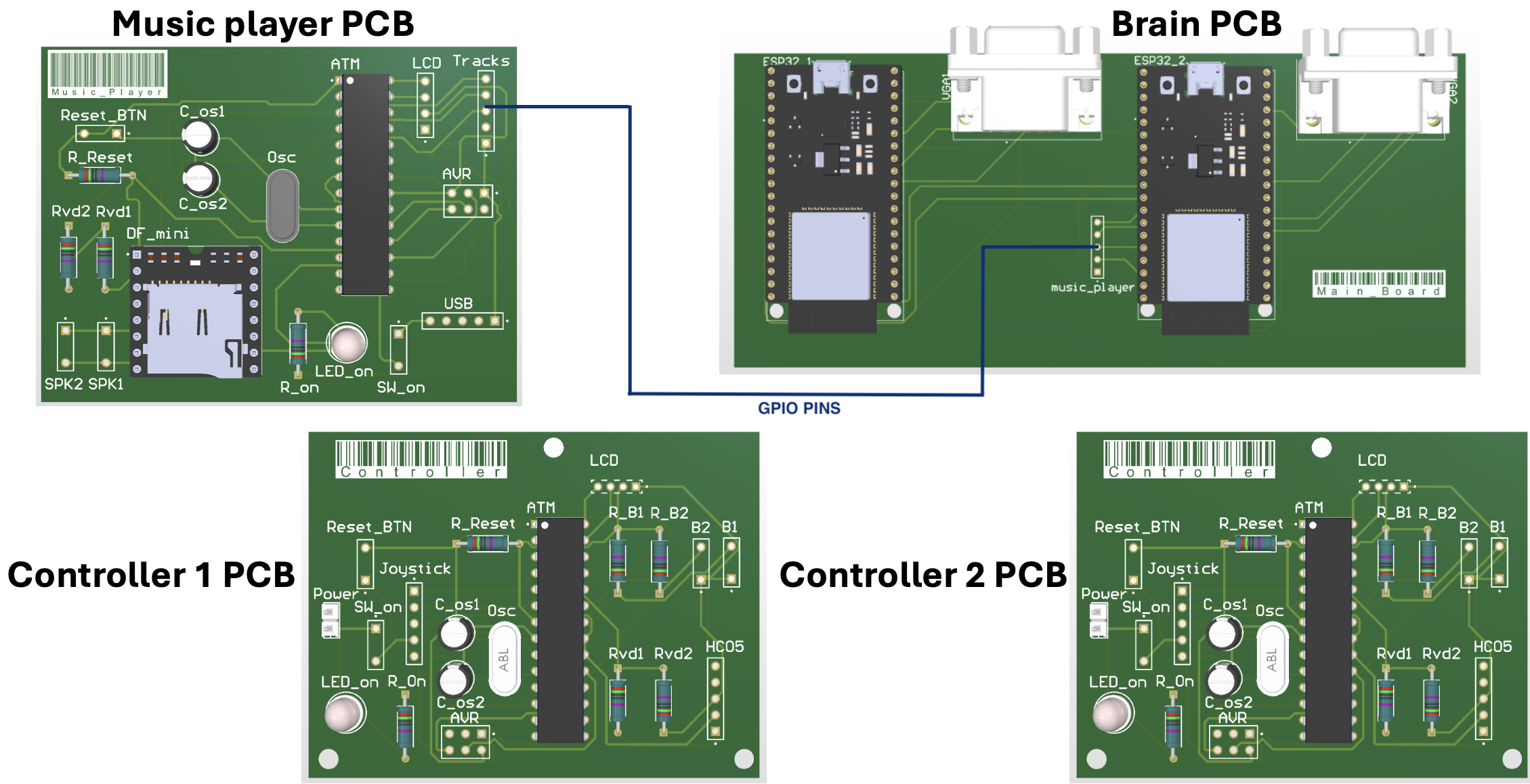
4. Schematic Capture & PCB Fabrication
We utilized Altium Designer for the complete ECAD workflow. Below is the documentation of the three distinct boards we designed, routed, and assembled for this project.
5. Verification & Performance Data
Rigorous testing was conducted to verify that the hardware met the demanding requirements of real-time gaming. The following data was collected during the final validation phase.
| Performance Metric | Requirement | Measured Result | Status |
|---|---|---|---|
| Controller Battery Life | ≥ 6 Hours | 72 Hours (Avg of 6 trials) | Exceeded |
| Input Latency | ≤ 100 ms | 38 - 52 ms | Pass |
| Bluetooth Pairing Time | < 10 Seconds | 4.02 Seconds (Avg) | Pass |
| VGA Sync Stability | 60 Hz ± 1% | 60.1 Hz | Pass |
| Power Rail Stability | 5V ± 5% | 5.0V ± 0.05V (Under Load) | Pass |
6. Engineering Challenges & Solutions
Challenge: The "Everything Everywhere" Crash
Problem: Running Wi-Fi (for multiplayer), Bluetooth (for controllers), and VGA generation simultaneously caused system-wide failure due to radio resource contention on the 2.4GHz band.
Solution: We completely removed Wi-Fi from the architecture. We replaced it with a hardwired UART link (GPIO 16/17) between the two ESP32s. This decoupled the multiplayer sync from the radio stack, resolving the crash and lowering power consumption.
Challenge: Audio Latency & Jitter
Problem: Handling audio directly on the ESP32 introduced jitter into the VGA signal due to interrupt overhead.
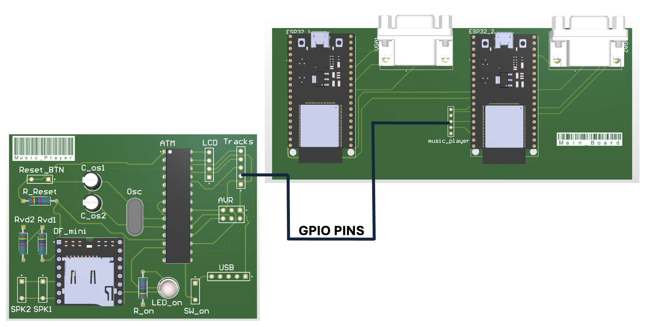
Solution: We designed a dedicated Audio PCB with its own ATmega328P. The main console simply sends a brief 27ms GPIO trigger signal, and the dedicated board handles the heavy lifting of MP3 decoding via the DFPlayer Mini.
7. Engineering Skills & Tools Applied
This project served as a comprehensive application of electrical engineering curriculum, requiring the integration of power, analog, and digital domains.