Low Voltage Residential Electrical Distribution & Lighting Design
1. Executive Summary & Engineering Scope
Project Context: The "Matrouh Residential Tower" is a high-density vertical development project. The structure features a complex load profile, integrating a Commercial Ground Floor with six typical residential floors and a Roof Services level. This project was not a simple drafting exercise; it was a comprehensive Systems Engineering challenge requiring the coordination of Lighting, Power, and HVAC loads into a unified, code-compliant infrastructure.
Technical Standards: The design philosophy was grounded in rigorous compliance. I utilized the Egyptian Code for Electrical Installations for local regulation adherence and IEC 60364 Standards for international best practices. All calculations—from cable derating to short-circuit withstand ratings—were cross-referenced with Dr. Mahmoud Gilany’s "Electrical Installations Reference" and technical specifications from the Elsewedy Cables Catalog.
Phase 1: Project Architecture & Standardization
A robust engineering project begins with data structure. Before drawing a single cable, I established a rigorous file management protocol based on the industry-standard "Project Tree" methodology.
1.1 File Management & Version Control
I segregated the project environment into IN folders (for received XREFs from Architecture and Mechanical disciplines) and OUT folders (for Electrical deliverables). This prevented version conflicts and ensured that I was always designing on the latest architectural footprint.
1.2 Architectural Cleaning Protocol
Received architectural backgrounds often contain excessive visual noise (hatching, furniture details, decorative dimensions). I performed a rigorous cleaning process:
- Explosion: Exploded nested blocks to access primitive geometry.
- Purge: Removed unused layers and line types to reduce file size.
- Layer Management: Assigned all architectural elements to a unified Background Layer (Color 252 - Gray). This layer was locked to prevent accidental modification.
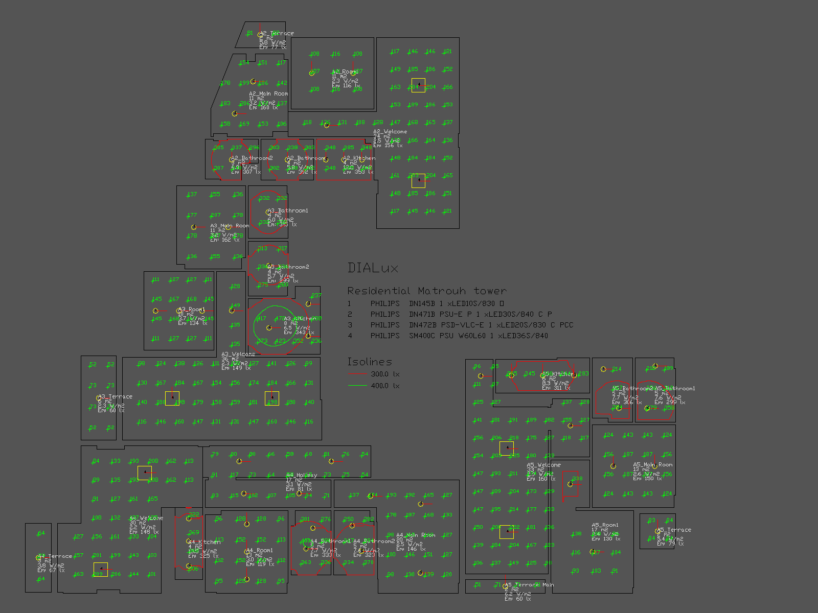
Phase 2: Computational Lighting Design
I rejected the "Rule of Thumb" approach in favor of computational verification. Using DIALux Evo, I simulated the entire floor plate to ensure every room met the lux levels required by the code.
2.1 Simulation Parameters
• Maintenance Factor (MF): 0.8 (LED depreciation)
• Work Plane: 0.75m (Standard desk height)
• Wall Reflection: 50% | Ceiling: 70% | Floor: 20%
2.2 Photometric Analysis
I integrated the Philips Lighting Plugin to select high-efficacy LED fixtures.
- Reception: 150-200 Lux (Warm White 3000K).
- Kitchens: 300-500 Lux (Cool White 4000K) for safety.
- Uniformity (U0): > 0.4 achieved in all zones.
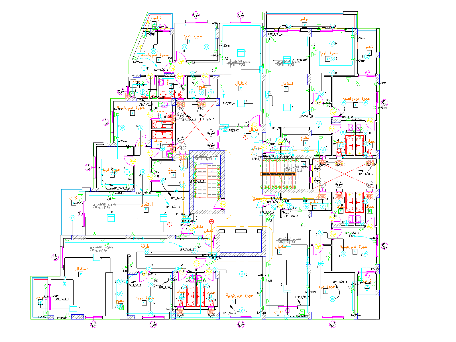
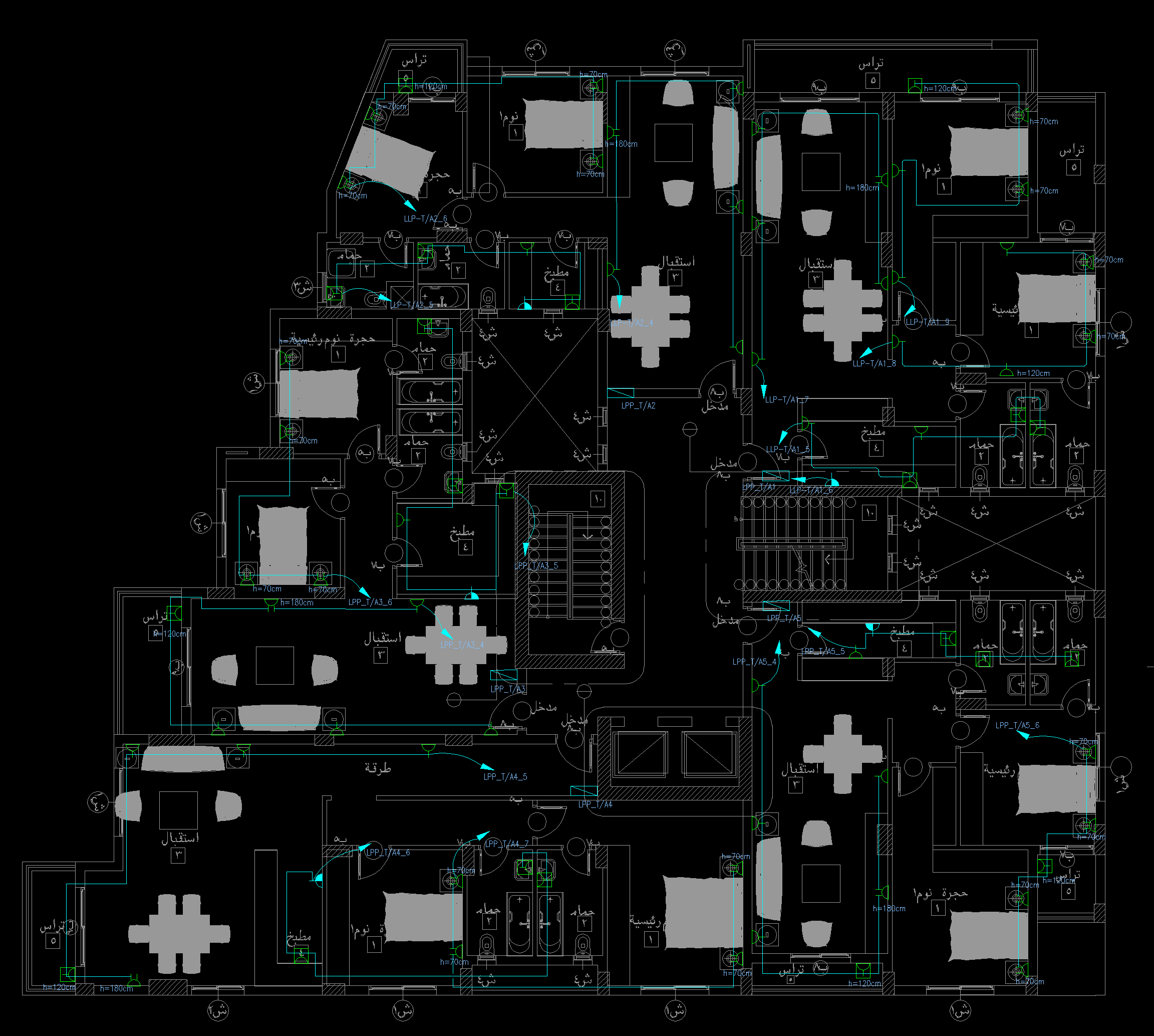
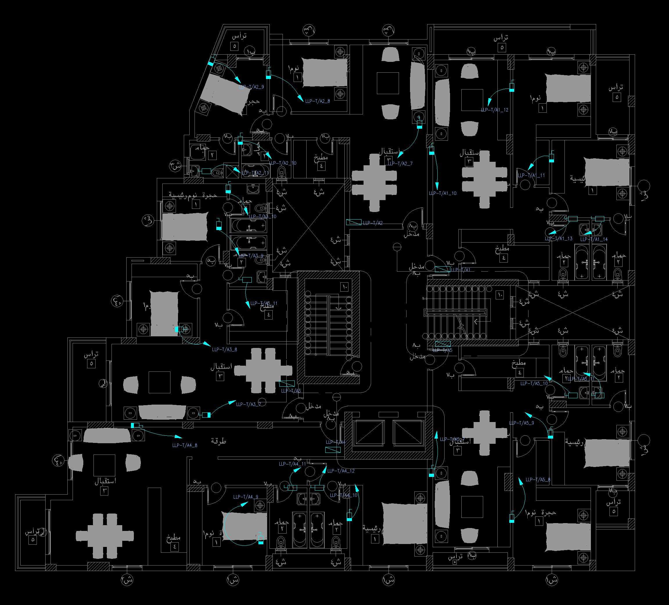
Phase 3: Lighting Layout & Circuiting
Once photometric calculations were approved, I exported the fixture coordinates back to AutoCAD Electrical to finalize the construction drawings.
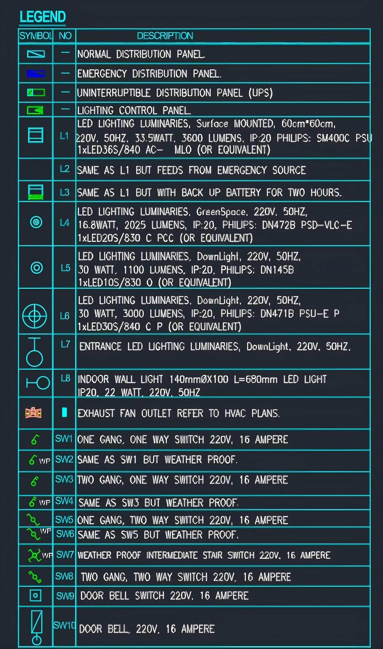
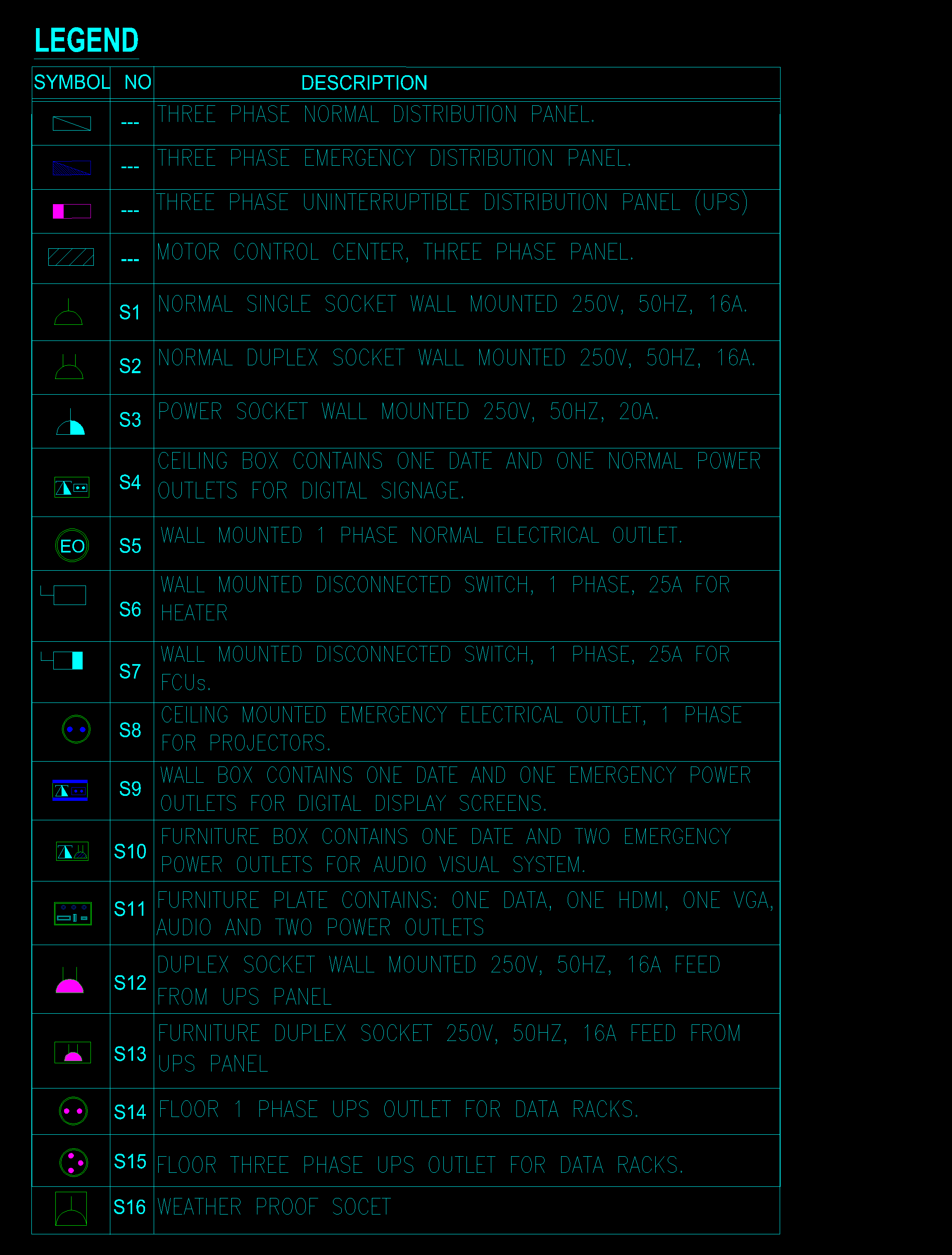
3.1 Standardization (The Legend)
The image on the right (Fig 3.2) shows the Project Standard Legend. I adhered strictly to these symbols to ensure that site engineers and contractors had zero ambiguity regarding mounting heights, lamp types, and IP ratings.
3.2 Circuit Reliability Logic
I applied a strict Circuit Segmentation Strategy:
No more than 3 rooms were placed on a single lighting circuit. This ensures that if a breaker trips due to a fault in one room, the entire apartment does not plunge into darkness—reliability through segmentation.
Constraint: Max Load per Circuit < 1200 VA.
Protection: 10A / C-Curve Breaker.
Wiring: 3x3mm² Cu/PVC wires in 20mm conduit.
Phase 4: Power Distribution Strategy
The power layout was engineered to balance user convenience with strict safety codes. I adhered to the "Furniture Layout" method to place sockets where they are actually needed.
4.1 Socket Placement & Heights
- General Sockets: 30cm AFFL.
- Wet Area Sockets: 120cm AFFL (Away from water).
- AC Isolators: 180cm AFFL (High wall).
4.2 The "3.6 Meter Rule"
I enforced the spacing rule: no point along a wall can be more than 1.8m from an outlet. This effectively means placing sockets every 3.6m to minimize the use of dangerous extension cords.
Phase 5: Mechanical Load Coordination
Electrical design cannot exist in a vacuum. I coordinated extensively with the HVAC drawings to ensure every mechanical unit had robust power delivery.
5.1 Heavy Duty Isolation
I placed dedicated Double Pole (DP) Switches (20A/32A) adjacent to every Split AC unit and Electric Water Heater.
Engineering Reason: This provides a local point of isolation, allowing maintenance personnel to safely service the unit without accessing the main panel.
5.2 Environmental Protection
Specified IP55 Weatherproof Isolators for balcony units and IP65 Isolators for Roof units to prevent water ingress faults.
Phase 6: Load Calculation & Panel Scheduling
This was the most mathematically intensive phase. I utilized advanced Excel schedules to size the breakers and calculate the Total Demand Load for the building.
6.1 Breaker Sizing & Diversity
Sized MCBs using a 1.25 safety factor. Applied IEC Diversity Factors to avoid oversizing the transformer.
| Load Type | Design Current | Breaker | Diversity Factor |
|---|---|---|---|
| Lighting | ~4-5 A | 10A (C-Curve) | 0.66 |
| Sockets | ~8-10 A | 16A (C-Curve) | 0.40 |
| Split AC | ~7 A | 20A (D-Curve) | 1.00 (None) |
6.2 Phase Balancing
I balanced single-phase loads across Red, Yellow, and Blue phases to minimize neutral current.
Result: Imbalance < 1% (R: 10.8kVA, Y: 10.7kVA, B: 10.8kVA).
Connected Load: 40.5 kVA
Demand Load: 32.3 kVA
Main Breaker: 100A 3-Phase MCCB
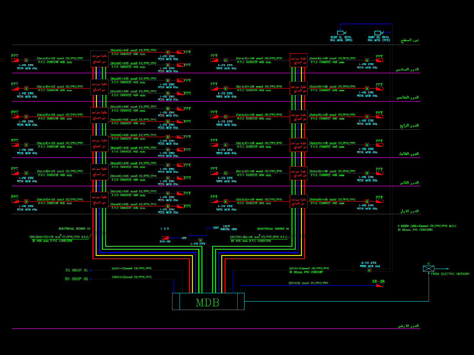
Phase 7: Infrastructure & Single Line Diagram
The final engineering step was designing the vertical backbone (Riser) that feeds all 6 floors.
7.1 Cable Selection & Derating Analysis
I selected Cu/XLPE/PVC cables from the Elsewedy Catalog. However, choosing cables based on "Air" rating is dangerous. I applied rigorous Derating Factors:
• K1 (Temp Factor): 0.9 (Ambient temp 40°C in shaft)
• K2 (Grouping Factor): 0.8 (Multiple cables in one tray)
Result: Sized main riser as 4x35mm² + 16mm² Earth.
7.2 Voltage Drop Verification
Verified that voltage drop at the furthest socket (Level 6) remained below 5%.
Calculation: Vd = (mV/A/m) × Ib × L / 1000 = 2.8% (PASSED).
Phase 8: Bill of Quantities (BOQ)
The final deliverable was a precise BOQ to allow contractors to price the project accurately. I utilized AutoCAD Data Extraction to ensure < 2% variance.
- Cabling: Measured linear meters + 10% waste factor.
- Accessories: Automatic block attribute extraction for socket counts.
- Panels: Detailed specs for IP ratings (IP42 Indoor / IP65 Roof).